ISSS608 2016-17 T3 Assign ERIC PRABOWO CUNDOMANIK Data
|
|
|
|
|
Contents
Dataset Description
Mini-Challenge 2 provides a three month set of data for you to analyze, covering April, August, and December 2016.
I. COORDINATES:
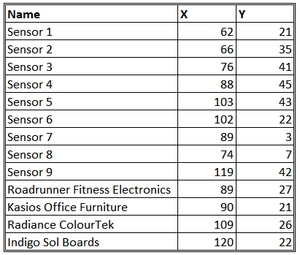
The factories and sensors locations are provided in terms of x,y coordinates on a 200x200 grid, with (0,0) at the lower left hand corner (southwest). The sensors map shows the locations of the sensors and factories by number for the sensors and by name for the factories. Some of the other features of the map (such as entrances and gates in that area) have been removed for readability. (Please note that the terms “sensor” and “monitor” are used interchangeably.)
The following are the factory locations:
Roadrunner Fitness Electronics: 89,27
Kasios Office Furniture: 90,21
Radiance ColourTek: 109,26
Indigo Sol Boards: 120,22
The following are the sensor locations:
1: 62,21
2: 66,35
3: 76,41
4: 88,45
5: 103,43
6: 102,22
7: 89,3
8: 74,7
9: 119,42
II. METEOROLOGICAL DATA
[Date, Wind Direction, Wind Speed]
Date: The date and time of the readings, local time with no change for Daylight Savings.
Wind Direction: The compass directions where the wind is originating from, using a north-referenced azimuth bearing where 360/000 is true north.
Wind Speed: The speed of the wind in meters per second.
Each of these reading is taken at the date and time provided.
III. SENSOR DATA
[Chemical, Monitor, Reading, Date Time]
Chemical: Which one of the four chemicals detected by the sensors
Monitor: Which one of the nine sensors picking up the reading
Reading: The air sensor detected amount in parts per million
Date Time: The date and time of day of the reading, local time with no change for Daylight Savings.
Data Preparation and Cleaning
1. Create X, Y coordinate Excel file for sensors and companies
2. Clean meteorological data
3. Duplicate meteorological data (wind data) for building the polygon shape in Tableau
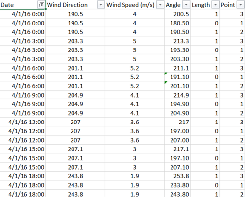
- Add 3 additional columns [Angle, Length, and Point]: new columns are specifically for building the polygon shape for the Wind Rose on the chart. Each of them are for building components of the lines of the Wind Rose, they are:
- Angle is Tripled with the additional +10 and -10 degree from the original data,
- Points identify the tripled Angles (original Angle: 2, -10 Angle: 1, +10 Angle: 3)
- Length means the length of the point stretched (only point 2 and 3 is set to 1)
- Angle is Tripled with the additional +10 and -10 degree from the original data,
- Triple the data: by adding 3 columns above, there should also be copying process of the data. Data should be copied 3 times for each of the angle, before applying formula to calculate the Angle and Length column.
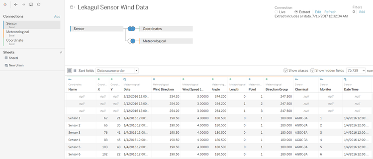
4. Connecting to Tableau with inner join method
- Going forward to Tableau, add the 3 flat files of the data (Sensor, Coordinate, and Meteorological in sequence). This will make Sensor as the key data point, and connect to both Coordinate and Meteorological data. For meteorological data used is the one tripled, or modified by copying the data 3 times for the polygon shape drawing on Wind Rose.
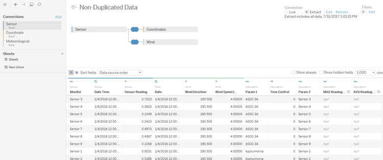
- Add another dataset in Tableau by joining a new combination, where the dataset is not tripled (as for the polygon shape drawing). Use the Sensor, Coordinate, and Meteorological (non-modified meteorological dataset).
Data Visualization Charts
[in progress..]
I. Line Charts for Sensor Readings
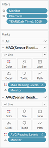
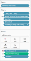
Line charts for sensor readings are measured by default sensor reading data. However, the coloration of the line charts, uses 2 different measurements following with the Sensor Readings number.
II. Wind Rose
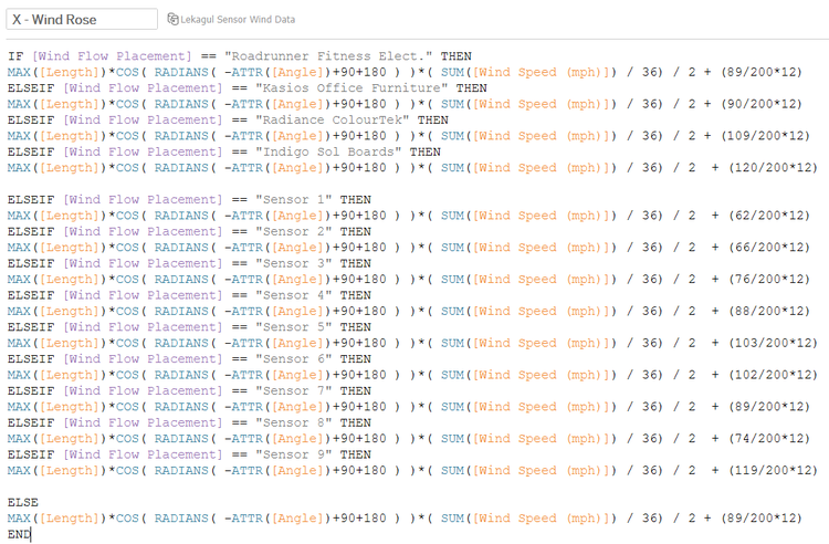
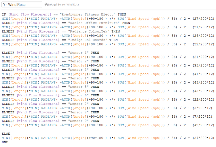
The wind rose X and Y coordinates are formulated from the data in Tableau. So, there are 13 Ifs for 9 sensors location and 4 factories in the map coordinates where the Wind Rose (or Coxcomb Chart) can be placed in the map view.
There are some formulation to build the Wind Rose data, where Length data indicates the construction of the Wind Rose with the additional -10 degrees and +10 degrees data explained previously. Then, it calculates the COS (for X axis) and SIN (for Y axis) to show the Angle of the wind. There are 90-degrees added in the map for Radians calculation purpose, and also 180-degrees added in the calculation as the wind comes from the directions. Third, the wind rose polygon is multiplied by Wind Speed that has been converted to Miles per hour (Mph) unit. All of the coordinates is divided further by 36 due to the multiplied dataset by 36 times after joining the data. Further division by 2 is to divide or reduced wind speed (wind rose 360 view half-diameter is reduced). Lastly, the last part of the calculations [x/200 + 12] and [y/200 + 12] means real coordinates of each factory or sensors (200x200 map) divided by 200, converted to miles unit map (12x12 miles).
III. Bar Chart
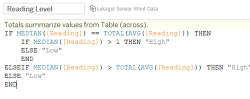
High and Low reading level formula for bar chart on the dashboard uses total average baseline to decide whether median of the reading (median is basically to aggregate 3 data points due to polygon drawing – median would be the original data itself).
IV. Line Chart for Wind Speed
Add line chart for windspeed with time data as X-axis and Windspeed (mph) as Y-axis.
V. Choropleth for Sensor and Chemical Readings
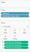
Prepare the variables of Choropleth plot of Sensor Detection Count. These sensors are further divided to different chemical substances count.
Put Chemical, and filter null years on the Filter part. Put Time Control X and Y to customize time filters, and put chemical to Rows.
